pengertian clean room ventilation

Heating, ventilating and air conditioning systems (HVAC) Clean room HVAC systems Although EVC is currently a single facet firm we can provide & or advise Clients in conjunction with our current associates in the other fields of the Building School & large hall comfort Workshop dust & fume extraction systems Industrial high heat capacity systems From utilising the original design drawings; installation drawings are produced. All ductwork & associated system components are itemised & scheduled appropriately to provide our Clients with a comprehensive Utilising clients original hard copy or scanned drawings we can re-produce into full electronic format drawing files. Utilising Clients drawings with the site condition modifications we can produce drawings for the inclusion in operation & maintenance manuals. As part of our documentation process EVC currently utilises: AutoCAD & AutoCAD LT ACADS-BSG CAMEL Air Conditioning Load Software

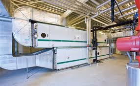
ASHRAE Duct Fitting Database Multiple Manufacturers equipment selection software Example of mechanical workshop layout drawing. Example of mechanical design layout drawing. Compressed Air & NItrogen Generation Services 3D Duct Layout for Hamilton Tafe Solar HVAC Project Drawings available upon request, please contact us for full size example drawingsEngine room ventilation is of great importance to the engine life. In many vessels, there is enough air for engines to burn their fuel, but not enough to cool the engine room as well. Since warm air doesn't hold as much oxygen, engines end up with less power, and less efficiency. Engines will need to burn more fuel in order to achieve the same power level. Air conditioning systems and engine room ventilation help keep the equipment in the engine room clean and in better working order. This translates to an increased engine life and a reduction in the required maintenance. Engine room heat doesn't just affect engines, it also damages generators, cooling, and electrical systems.

Engine room ventilation systems consist of both intake fans, which insert combustion air and cooling air, and exhaust fans, which pull out cooling air only. In case the temperature in the engine room rises, the exhaust fans start to pull out cooling air. Consequently, the resulting depression in the engine room ramps up the intake fans.A marine engine room ventilation system is often equipped with mist eliminators. Mist eliminators are designed to extract mist and seawater from intake air. These are the grills you typically see at, or inside, the engine vents. These can be built to fit any size or shape of vent and play a major role in keeping water out of the engine room by reducing the amount and size of the water droplets in the air coming into the space. Salty mist becomes steam in the 300- to 400-degree air inside turbochargers, instantly vaporizing water and crystallizing salt. This causes minerals to be deposited on turbo blades and intake air coolers get clogged. Mist eliminators can prevent this process.

The greater need for proper ventilation can be attributed to the advancement in turbocharged diesels as well. With more air needed to allow the engine to achieve a proper combustion cycle, the design and implementation of the properly sized fans and vents are increasingly more critical. This is especially true on refits when a new set of higher-horsepower engines is going into a tight space. The engines will most likely choke if you wait until after the installation to consider the air requirements of the new power.
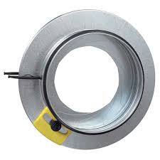
activtek air purification systemFire dampers are also a great addition to any engine room's air-handling system.
therapure air cleaner instructionsDampers are multi-blade metal louvers that will snap shut and cut off the intake air when the vessel’s fire system engages.
himedia air purifier
Cutting off a fire's air is one of the fastest ways to kill or contain it.In case you would like to get more information about our engine room ventilation systems, don’t hesitate to contact us. Our skilled employees are eager to help you. See also: Underfloor air distribution Displacement ventilation (DV) It is a room air distribution strategy where conditioned outdoor air is supplied at a low velocity from air supply diffusers located near floor level and extracted above the occupied zone, usually at ceiling height. A typical displacement ventilation system, such as one in an office space, supplies conditioned cold air from an air handling unit (AHU) through a low induction air diffuser. Diffuser types vary by applications. Diffusers can be located against a wall ("wall-mounted"), at the corner of a room ("corner-mounted"), or above the floor but not against a wall ("free-standing").[2] The cool air accelerates because of the buoyancy force, spreads in a thin layer over the floor, reaching a relatively high velocity before rising due to heat exchange with heat sources (e.g., occupants, computers, lights).
[3] Absorbing the heat from heat sources, the cold air becomes warmer and less dense. The density difference between cold air and warm air creates upward convective flows known as thermal plumes. Instead of working as a stand-alone system in interior space, displacement ventilation system can also be coupled with other cooling and heating sources, such as radiant chilled ceilings[4] or baseboard heating. Displacement ventilation was first applied in an industrial building in Scandinavia in 1978, and has frequently been used in similar applications, as well as office spaces, throughout Scandinavia since that time.[1] By 1989, it was estimated that Displacement ventilation comprised the 50% in industrial applications and 25% in offices within Nordic countries.[5] Applications in the United States have not been as widespread as in Scandinavia. Some research has been done to assess the practicality of this application in U.S. markets due to different typical space designs[1] and application in hot and humid climates, as well as research to assess the potential indoor environmental quality and energy-saving benefits of this strategy in the U.S. and elsewhere.
Displacement ventilation has been applied in many famous building such as the Suvarnabhumi International Airport in Bangkok, Thailand, the NASA Jet Propulsion Laboratory Flight Projects Center building,[6] and the San Francisco International Airport Terminal 2 among other applications. The thermal plumes and supply air from diffusers, which determines the velocity of airflow at floor level, play an important role in DV systems.[7] It is necessary to carefully set the airflow rate from the diffuser to avoid drafts. Due to the unique properties of thermal stratification, Displacement ventilation is typically used for cooling rather than for heating. In many cases, a separate heating source, such as a radiator or baseboard, is used in during heating periods. Displacement ventilation is best suited for taller spaces (higher than 3 meters [10 feet]).[2] Standard mixing ventilation may be better suited for smaller spaces where air quality is not as great a concern, such as single-occupant offices, and where the room height is not tall (e.g., lower than 2.3 meters [7.5 feet]).

Displacement ventilation systems are quieter than conventional overhead systems with better ventilation efficiency. Hence, it could enhance indoor air quality and provide desirable acoustic environment. Displacement ventilation systems are appropriate in space where high ventilation is required, such as classrooms, conference rooms, and offices. Displacement ventilation can be a cause of discomfort due to the large vertical temperature gradient and drafts.[8] According to Melikov and Pitchurov's research, sensations of cold caused by vertical temperature difference and draft are usually occurred at the lower leg/ ankle/ feet region, while warm sensations at the head are reported.[9] The research also indicates, that the draft rating model could predict the draft risk with good accuracy in rooms with displacement ventilation systems. There is a tradeoff inherent in these two issues: by increasing the flow rate (and the ability to remove greater thermal loads), the vertical temperature gradient can be reduced, but this could increase the risk of drafts.

[1] Pairing displacement ventilation with radiant chilled ceilings is an effort to mitigate this problem.[10] According to some studies, displacement ventilation systems can only provide acceptable comfort if the corresponding cooling load is less than about 13 Btu/h-sf or 40 W/m2. One benefit of displacement ventilation is possibly the superior indoor air quality achieved with exhausting contaminated air out of the room. Better air quality is achieved when the pollution source is also a heat source. Some studies have demonstrated that displacement ventilation may save energy as compared to standard mixing ventilation, depending on the use type of the building, design/massing/orientation, and other factors.[1] However, for the evaluation of energy consumption of displacement ventilation, the numerical simulation is the main method, since yearly measurements are too expensive and time. Hence, whether displacement ventilation could help with saving energy is still debated.In general, displacement ventilation is attractive to the core region in a building since no heating is needed.

However, the perimeter zones require high cooling energy. Different guidelines have been published to provide guidance on designing displacement ventilation systems, including: Among guidelines listed above, the one developed by Chen and Glicksman are aimed specifically at fulfilling U.S. Standard. Below is a brief description of each step of their guideline. Step 1) Judge the applicability of displacement ventilation Step 2) Calculate summer design cooling load. Step 3) Determine the required flow rate of the supply air for summer cooling. Step 4) Find the required flow rate of fresh air for acceptable indoor air quality. Step 5) Determine the supply air flow rate. Step 6) Calculate the supply airflow rate. Step 7) Determine the ratio of the fresh air to the supply air. Step 8) Select supply air diffuser size and number. Step 9) Check the winter heating situation. Step 10) Estimate the first costs and annual energy consumption. ^ a b c d